This Technical Note describes the two kinds of protection against lightning damage in decoder based 2 or 3 wire irrigation control systems.
When properly installed, lightning protection in decoder systems will generally be stronger than that found in smaller multi-wire systems. The exception is pedestal-mounted multi-wire, where extensive extra lightning protection components are housed within the pedestal.
In decoder based systems, there are only two (or 3) wires to protect, thus there is more space to fit tough protection components within the controller and in each decoder.
Tropical Strength Decoders
- Ultra-high immunity to lightning.
- No earth stakes needed. Much easier installation.
- Long solenoid runs will not degrade lightning immunity.
- Not overly affected by cable leakage to earth.
Lightning Protection
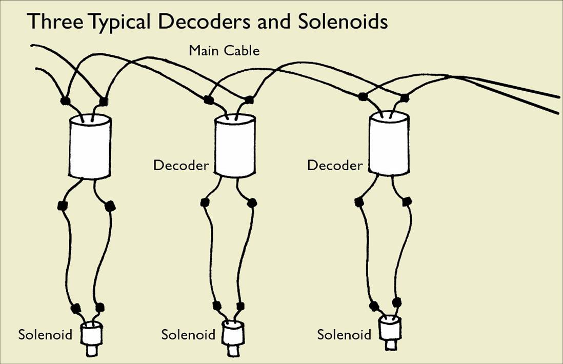
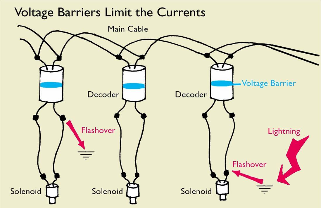
The wires on some decoders do not come out of the other end, but this diagrammatic representation helps understand the principles better.
‘Main cable’ is the common 2 wire path around the site to all the decoders.
The black dots represent waterproof connectors, such as 3M DBY or Connector King equivalents.
When solenoids and decoders coexist in the same valve box, just one set of joints is needed.
Lightning Damage Mechanism
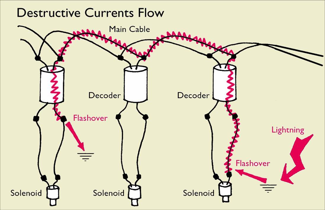
Where lightning strikes, the ground goes up to about 2 million volts with currents in the region of 25,000A-100,000A. Although the eye only sees one flash, there are typically 5-10 such strikes in quick succession. No affordable lightning protection scheme will withstand such a direct hit.
The more common event is a surge caused by a nearby strike. In this instance the GROUND goes up to a potential of between 6KV-10KV. Flashover from the ground onto the wring usually occurs at a wiring joint where the insulation is at its weakest. If this is a solenoid joint, the currents, typically 10,000A-30,000A flow through the decoder, destroying it, and travel around the main cables seeking another path to go back to ground.
Damage may also occur when lightning discharges between two oppositely charged storm clouds that are further apart than they are above the ground. (Sheet Lightning). In this case, the cables pick up the surge directly.
Lightning Protection Stakes
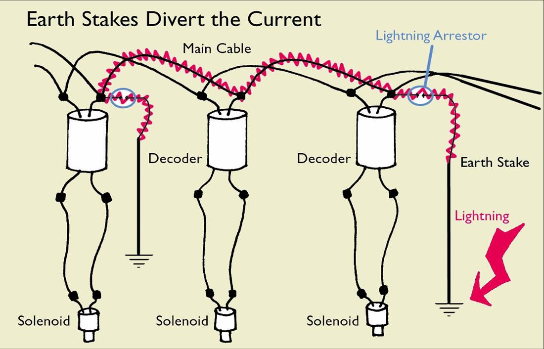
Nearly all manufacturers of decoders rely on the bypass principle, using earth stakes to shunt destructive currents around their decoders. In some form, they use Gas Discharge Tubes (GDT) which conduct at around 90V – 120V. These tubes may be incorporated inside the decoder, or be external. In all cases to be effective, an earth stake must be used.
Note that the solenoid must be physically near the decoder. Most manufacturers quote a few 10’s of feet.
This technique makes high currents more likely in the main cable, thus putting it and its cable joints at greater risk.
The Alternative ‘Floating’ Lightning Protection
The alternative ‘floating’ technique, relies on the construction of a voltage barrier within the decoder that can withstand 10KV and limit currents through the decoder to an amount that can be withstood by the PCB tracks without damage.
No earth stakes are needed around the cable path or next to each decoder. However, it is important to put just one earth system in, next to the controller. This must be separate from the building earth system.
With this technique, it is not necessary to limit the distance between decoder and solenoid. In many installations this can be 1000ft with no diminution of lightning protection to either decoder or solenoid.
Peak currents in the main cable are usually smaller than with the earth stakes method, thus less likely to be damaged.
Separating Decoders & Solenoids
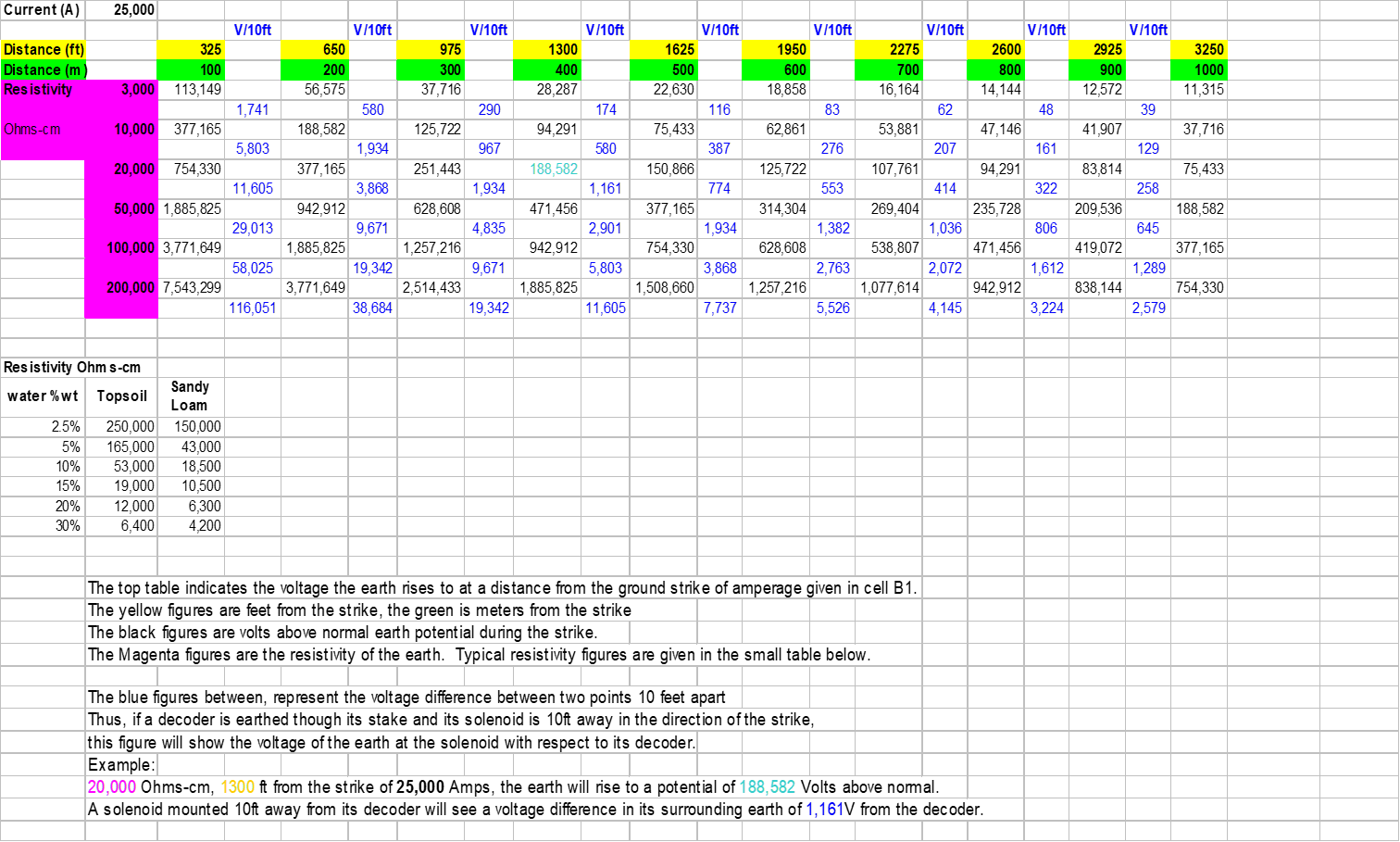
When an earth stake needs to be connected to the decoder for lightning protection, it is important to keep the solenoid physically near the decoder. The chart above gives figures for what happens when the solenoid is remote from the earth-staked decoder.
On the above main table, the notes explain the various entries and should be read first.
It is important to note that the above figures are simplified to assume a constant earth resistivity with depth. If the upper layer of soil is of a fairly low resistivity (topsoil) and the underlying is high (e.g. bedrock) the voltage stresses are much higher as the lightning currents are concentrated into the upper layer, producing much higher voltage gradients.
The important conclusion is that with all decoder systems that use earth stakes, the solenoid MUST remain within a few feet of the decoder for protection to be effective. Where a decoder has an earth wire, it is mandatory to earth stake it.
With the alternative floating lightning protection system, this limitation does not apply, so the solenoid can be a great distance from the decoder with no loss of lightning protection. Such a system is used on the Underhill and Tonick Watering range of decoders.
The Lightning Generator
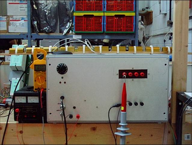
All decoder and controller products are tested using this equipment, which was home-built.
Several iterations of new controller and decoder design are usually necessary before the product can be released for sale with a known lightning immunity.
For this reason, Underhill and Tonick 2 wire products are warranted against lightning damage.