
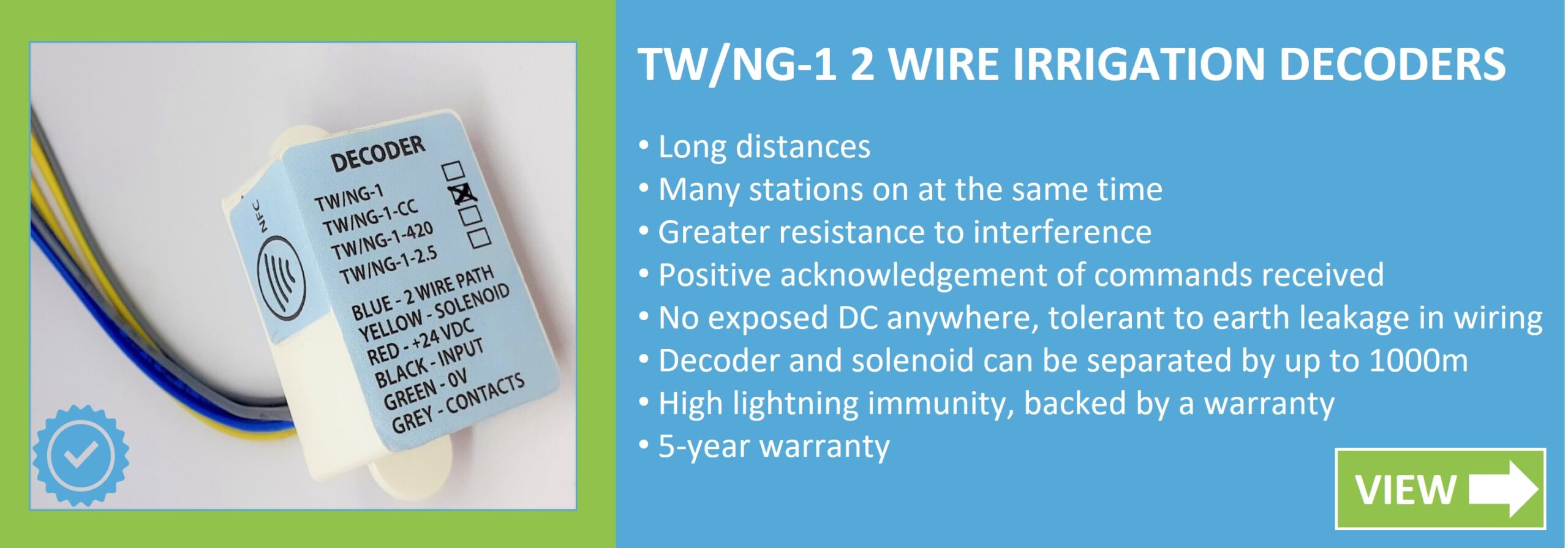
View our range of irrigation decoders here.
Tony Ware gained a B.Sc. in Electronic Engineering at the University of Manchester Institute of Science and Technology.
His career spans 4 decades designing electronic equipment for the medical, scientific and process control industries.
He entered the irrigation industry in 1995, designing functionally equivalent irrigation decoders to 8 different 2 and 3 wire control systems. These are currently fitted to 2/3rds of the UK and Ireland’s golf courses.
Since then, he has designed 7 different irrigation controllers.
He invented and introduced the world’s first 2Wire plug-in converter module to retrofit a multi-wire irrigation controller giving hybrid operation.
He has written this article to share everything you need to know about 2 Wire Decoder Technology Irrigation Systems.
2Wire Advantages and Weaknesses
Multi-Wire Irrigation, one wire and a common to each solenoid.
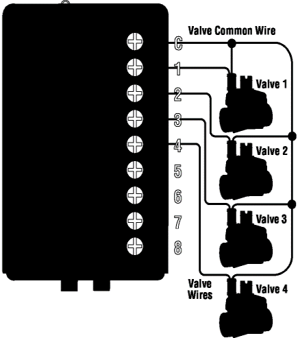
The conventional way is to have a controller with many terminals, each with a wire to leading to an individual solenoid on an electrically activated water valve. A ‘common’ wire completes the circuit, daisy-chaining to the other side of each solenoid, then back to the controller. This type of controller is called Multi-wire.
Multi-wire cable faults, easy to diagnose
The main advantage of faultfinding a multi-wire system is the fault is normally confined to one, or a couple of valves. Other valves are not affected.
The only exception is, if the common is cut, all valves past the cut will not operate.
Faultfinding equipment needed is minimal, a $20 digital multimeter is usually adequate.
A direct path from the controller to the solenoid allows cable tracing techniques to locate lost valves (grassed over).
- Short circuit between one valve wire and the common?
- Short circuit between 2 valve wires
- Open circuit on one valve wire or open circuit solenoid.
- Open circuit in the common wire
- Controller skips the station, reporting a fault.
- Both valves come on when each is demanded.
- The valve does not operate. Most controllers do NOT report a fault
- All stations beyond the open no longer work
Multi-Wire Disadvantages
Although simple to understand, this method suffers from several significant disadvantages:
- The cost of the wire and installation labour is significant.
- If the bundle of cables is damaged, it is a skilled and time-consuming job to join them all up again (and get it right!).
- New valves cannot be added without routing an extra wire for each, right back to the controller.
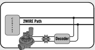
Typical 2 wire decoder system
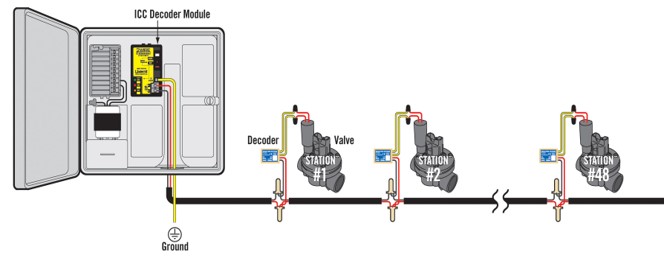
2Wire irrigation systems rely on uniquely pre-numbered decoders connected along a common 2 wire path, each connected to a solenoid valve. The controller feeds typically 24VAC down the path, combined with a digital signal commanding a decoder to turn the solenoid on or off. The decoder, whose number matches the signal, obeys the command. All the other decoders ignore the signal.
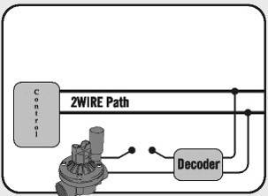
2Wire. Easy expansion without trenching back to the controller
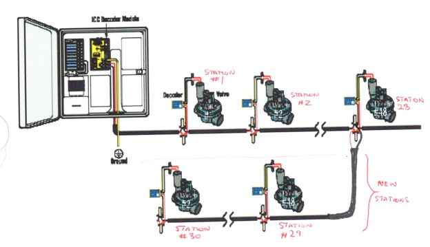
Expansion of the network is easy, with further decoders and cable being spliced anywhere along the existing path. The number in each new decoder must be unique.
Other 2Wire Advantages
- Much lower cabling price per foot
- Significantly quicker installation, could be 1/3 time
- No wasted onward conductors as with multi-wire and no spare conductors needed.
- Overall project costs may be lower, because of 1-3 above, even when factoring in the decoder costs
- Simple repair to damaged cables. Just 2 wires to rejoin. Many systems are polarity independent on the 2 wire path, no need to even match the colours.
- Simple checkout of entire cabling system in ½ hour.
2Wire Disadvantages
- Extra lightning protection ground stakes and modules needed on some, but not all systems
- Some, but not all systems require special 14AWG cable
- Some systems are sensitive to 2wire cable leakage to ground. These cannot be used on old wiring.
- Difficult to locate cable shorts, opens and leakage to ground without a leakage current clamp meter and faultfinding transformer.
- Some decoder systems, particularly those which use DC on the solenoid, block cable tracing past the decoder, making finding lost valves more difficult.
Fault tracing 2Wire systems
- With these two pieces of equipment, fault tracing shorts, opens or cable leakage is fast and simple.
- Faster than faultfinding in multi-wire systems!
- Usable equally well with all decoder systems.
- The total outlay for this is around $600 or less, to the contractor.
2Wire cable faults Short circuit on the 2 wire path
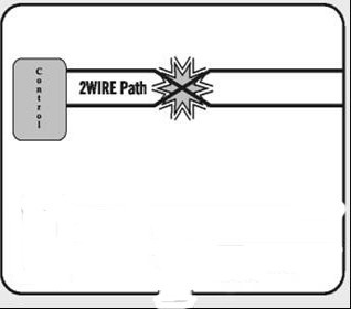
- High currents flow and the controller shuts down to protect itself.
- It is not obvious where the short is.
2Wire cable faults - Open circuit in the main 2 wire path
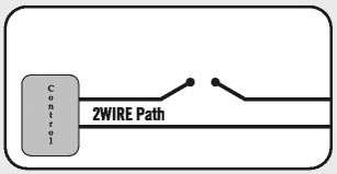
- All decoders up to the open will work, those beyond will not
- Equivalent to a break in the common line in a multi-wire system
2Wire cable faults - Short circuit solenoid
- Short only shows up when a decoder is operated
- Sometimes stops the system working afterwards due to voltage loss down the main 2 wire path, preventing an off command from reaching the decoder.
- Some 2Wire systems are more clever, will report a fault and not try to turn on the solenoid
2Wire cable faults - Open circuit solenoid or dead decoder
- Station does not respond
- Can also be a dead decoder
- All decoder systems will report a fault
- In contrast, most Multi-wire systems will not report an open solenoid
2Wire cable faults - Cable leakage to earth
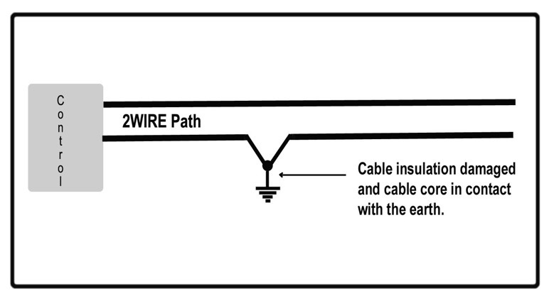
When a cable or joint is not well insulated, some electricity can leak to ground (earth). This causes problems for some makes of controllers, either refusing to control at all, or sometimes giving erratic operation, leading to the controller being suspect.
The immunity to cable leakage varies considerably from make to make. Some controllers will stop working, others will be indifferent to quite bad leakage. The latter type will work into retrofit sites without the need to re-cable.
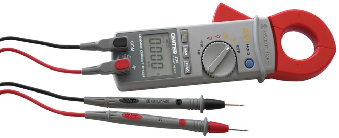
Diagnosing 2Wire cabling faults - Current Clamp Multimeter
The essential tool the 2Wire service engineer must own. To be of use, must be a ‘leakage’ clamp meter. Ordinary ones not sensitive enough.
When used with a powerful 24VAC transformer will quickly diagnose and locate all 2 wire faults. A spare solenoid completes the test equipment needed.
How to measure a current without breaking the wire
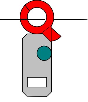
Currents are measured by opening the red jaws by pressing the red trigger with the thumb and clamping the jaws around the wire.
Normally place the clamp around just one of the wires, not both.
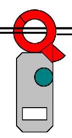
It is important to understand that if both flow and return wires carry the same current and are placed inside the jaws, the multimeter will read zero.
When the test equipment system is set up for testing earth leakage, the flow and return will have different currents in them as some is leaking back through the ground, therefore the meter will read the difference in the two conductors = leakage through the earth.
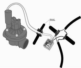
Testing a decoder
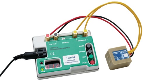
- Most decoder manufacturers offer a decoder tester
- The tester may be used to enter the decoder’s station number before installation
- To be of use, the tester should be low cost or not enough will be available for each crew
- Some decoder systems use factory pre-numbered decoders. Each number must be entered into the controller for it to know what to send when commanding a station on or off.
- Other systems discover decoders, but their locations must be noted by the installer, otherwise no one knows what they water!
- Some manufacturers offer a programmer/tester that can be used on the decoder when wired into the 2wire path. This is very convenient, but adds cost to each decoder and is itself quite costly.
Fault tracing short circuits
Most controllers will refuse to power up a 2-wire path that has more than a certain amount of load or leakage on it. Fuses may blow, software may shut the cable down, or even worse, a drive transistor in the controller may overheat.
If at any time, faults are suspected, or the controller behaves erratically, it is best to test the wiring to the decoders using a power transformer (as illustrated) and a current clamp meter.
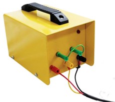
Using the Transformer
A big power transformer, such as the one illustrated in the previous slide, plugs into the 115V power and produces 30V AC at up to 6 Amps to power up the 2 wire path.
30V AC is not known to damage any decoder system.
The field wiring is removed from the controller and the transformer's output is connected to it instead. Because of its size, the transformer can still produce a powerful voltage in the presence of quite serious field wiring faults.
Because it lacks signalling circuitry, the transformer itself cannot turn decoders on or off. However, this is not a disadvantage for the sort of faults that would shut down or damage a controller.
When used with a current clamp meter, digital voltmeter and a spare solenoid, the transformer allows fault finding with the minimum of effort and confusion.