Irrigation solenoids are used in control valves to open a pilot hole. This allows water pressure to decrease on the top side of a diaphragm. The diaphragm is then pushed away from the seat by the water pressure below so water flows through the valve to the sprinklers etc.
To understand solenoid action, it is necessary to distinguish between permanent and temporary magnetism. In the following figure, the rod magnet is made of a material that holds its magnetism permanently, such as some steels. Any magnet has a North and South Pole; whatever the shape of the magnet they cannot be on their own, always as an NS pair. In the case of this figure, the North is at one end and the South is at the opposite.
The tacks in this example are made of soft iron. This can be magnetised, but as soon as the magnetic force is taken away, their magnetism disappears. They can be thought of as temporary magnets and are also called soft magnets.
It is important to understand that the tacks will be attracted with the same amount of force by either the North or South pole.
Electromagnets
Electromagnets work very similarly to permanent magnets. To make one, simply wrap an iron rod with insulated wire and run current through the wire, as shown in Figure 11. The iron rod develops a magnetic field, and North and South magnetic poles.
Figure 11. Electromagnet
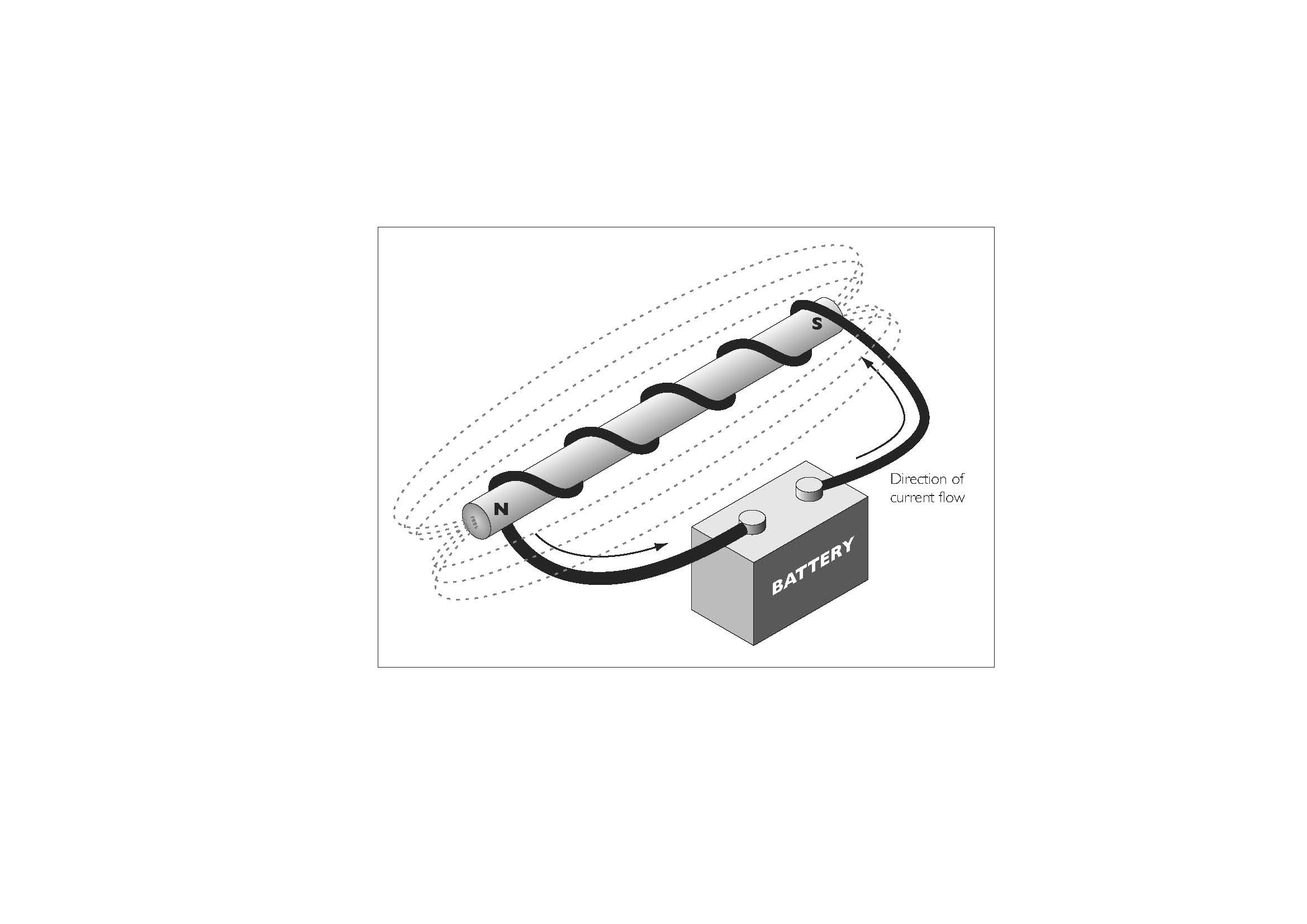
The electromagnet has two advantages over the permanent magnet.
- By adjusting the amount of current flowing through the wire, the strength of the electromagnet can be controlled. (used by Rain Bird for instance)
- By changing the direction of current flow, the poles of the electromagnetic can be reversed. In the diagram above, switching the leads on the battery terminals would change the direction of current flow. This is used in Latching Solenoids.
Connecting the leads to an AC source of 50 or 60Hz would switch the direction of current flow automatically. In this case, the N and S poles would reverse positions 50 or 60 times a second.
It is important to understand that temporary magnet, like the tacks, will be attracted by the same amount of force to either a North or South pole. Therefore, apart from a very small interval when the applied voltage passes through zero, there will always be an attracting force on the temporary magnet.
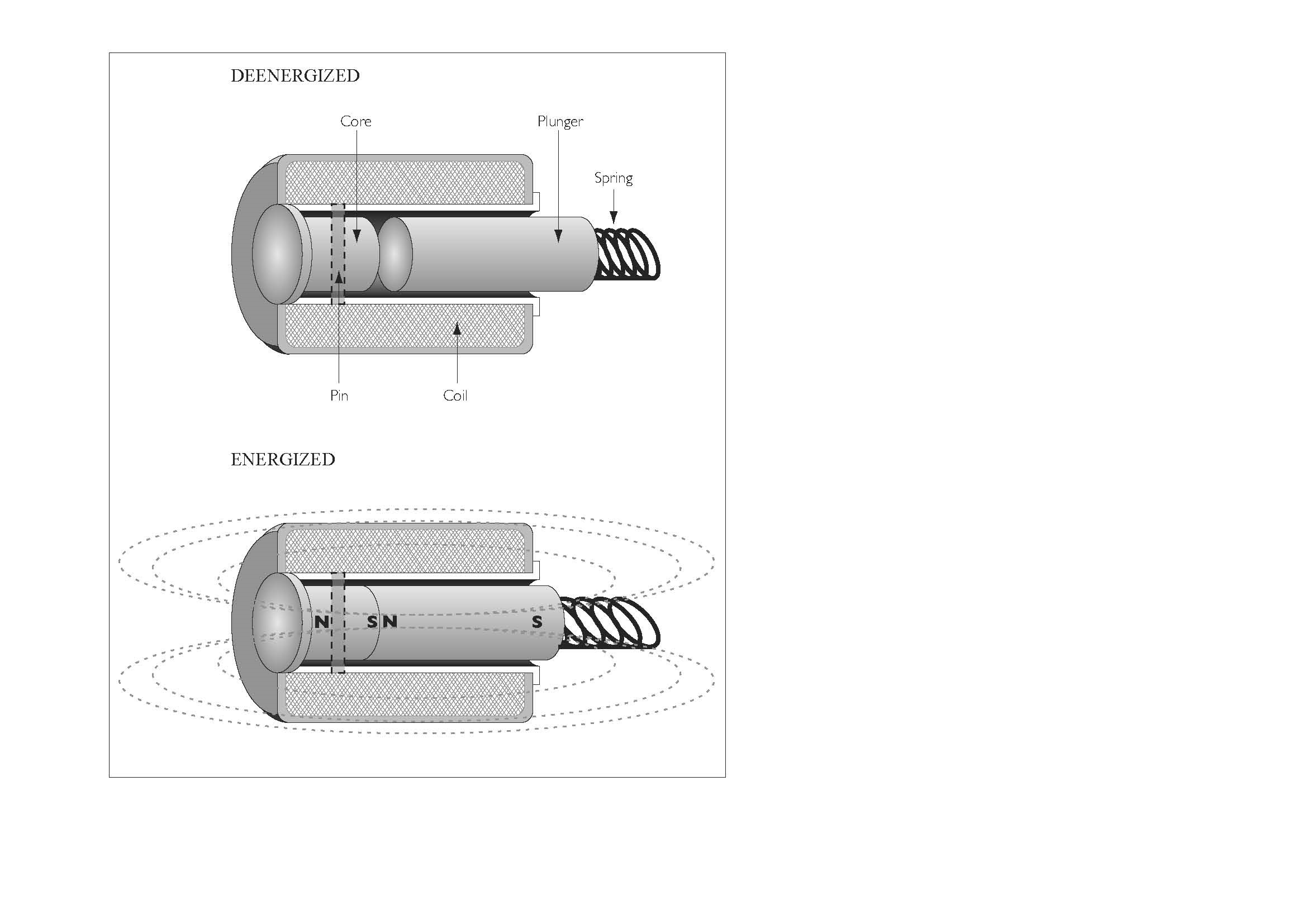
The following diagram depicts a solenoid. The plunger is a temporary magnet or soft magnet. It is held away from the core by the action of the spring.
In a real solenoid, the spring is often in a different position as this one would get in the way of sealing the pilot hole. However, wherever positioned, the spring’s action is the same, it holds the plunger out.
The pin is also a soft magnet (in a normal solenoid, more on latching solenoids later).
When the winding has a voltage applied, the core and the plunger become magnets. This attracts the plunger and sucks it up against the action of the spring. In the diagram, a DC voltage has been applied and the core nearest the plunger has become a South pole. The nearest end of the plunger has also become a North pole so the two attract. “Opposite poles Attract”.
If instead AC is applied to the coil, the poles would oscillate between N and S. However because the amount of attractive force does not differ whether it is an N or an S, there is still an attraction. Because of the mechanical inertia of the plunger, the short time that the force ceases when the AC voltage passes through zero, the plunger does not fall out. However, you can sometimes hear a plunger buzzing when the applied voltage is too low. In this case, the plunger is starting to move away from the core pin and then clicking back in again as the voltage increases.
Latching Solenoids
These are used with battery-powered systems where the continuous power needed to hold a valve open is not available without exhausting the battery in a short time.
How a magnetic latching solenoid valve works
Magnetically latching solenoid valves employs magnets and electrical current to affect operations at the expense of very little electrical power.
When electrical current is applied to the coil, based on the polarity of magnet and direction of current flow valve is latched or de-latched.
When the current polarity is reversed, valve latches if in de-latched position and vice versa.
In the above diagram, a latching solenoid would have the core as a permanent magnet, but the plunger would still be a temporary one. The force of the spring would keep the attraction of the core from drawing in the plunger. If however a DC voltage was applied to make the plunger nearer the core a North pole, the extra attraction would pull the plunger in.
Once engaged, and the DC removed, the force of the permanent South pole in the core would keep the plunger engaged against the force of the spring. Visualize the force the fridge door magnet keeping the door closed compared to when it is a little bit open. Thus only a short pulse of DC is required to latch the plunger in.
When the solenoid needs to be de-energised, a pulse of DC of the opposite polarity is applied to the coil. This induces a South pole next to the core pin. As “like poles repel” the plunger is forced away from the core and the spring keeps them apart when the DC is removed.
Solenoid Power Reduction
Remember the fridge door? A good pull is required to part the magnet in the fridge from the one in the door when they are close together. Once they are pulled apart, even a little way, the force decreases dramatically.
Using the same solenoid diagram as before, with soft magnets for the core and the plunger:
If DC is applied to pull the two together, because the force is much greater once they are touching, the amount of DC can be reduced to quite small values before the spring overcomes the attraction and pulls the plunger out again.
This is very useful if you want lots of solenoids energized on the same wire because if the holding power is reduced there is more to go round for others to be turned on. Note that full power is required to start the pull, it can only be reduced once the solenoid plunger is fully in.
This system does not work with AC because the attractive force varies during the cycle and falls to zero twice each cycle as the AC volts goes through zero on its way to the opposite polarity.
Note however that the engineering advantage gained by this clever technique brings its own problems.
- DC on field wiring causes electrolytic action if exposed copper wires come into contact with wet soil. Good cable and joint insulation is mandatory.
- The controller has to apply the full DC power for the correct amount of time to make sure the plunger is fully in before reducing the DC voltage. Controllers which use this technique may have to be ‘tuned’ depending on the make of solenoids fitted.
- Because of potentially destructive electrolytic action caused by field cable leakage to the earth, controllers which employ this technique will refuse to irrigate if they detect leakage. It must be located and rectified before watering can continue.
Solenoid Power Consumption
This section refers to AC solenoids only. DC latching solenoids and straight DC solenoids are not covered here.
The nominal operation voltage of a solenoid is 24V ac.
Most makes of 24V solenoid need 18V or 19V ac minimum, to pull in against 10 Bar water pressure. The voltage needed decreases with less water pressure. Consult the manufacturer’s charts for the exact figure.
Two power consumptions are normally quoted; the continuous power in Watts or VA and the surge power. To get the current consumption, divide the Watts or VA by 24. This will give you the current consumption in Amps.
Typical figures
- Holding current: 220mA (0.22A) 5.3W
- Surging Current: 400mA (0.4A) 9.6W
- Resistance (using a multi-meter): 35 Ohms
Surge Current
Solenoid coils have both a DC and an AC resistance which add up, making the current through the coil smaller than the measured DC resistance would first suggest.
When the plunger is out, the AC resistance is much smaller than when it is in. Therefore, as the plunger starts to move, the current consumption of the coil is much higher (e.g. 0.4A). However, as soon as the plunger engages with the core, the AC resistance increases dramatically and the current consumption falls to the holding figure (e.g. 0.22A). This action normally takes place in a fraction of a second.
It is important to note that the voltage across the solenoid must be greater than the minimum needed during the surge; otherwise the plunger will not pull in properly.
Wire Sizing Guide
It is important to ensure the solenoids have enough power to pull in their plungers at maximum water pressure.
A controller with decoders has to share solenoid power between solenoids on a common two wire cable. A basic controller does not apply solenoid current reduction techniques or DC. Thus the full AC volts are applied to the solenoid and remain there for the whole time it is on. The advantage of this is that electrolytic action does not happen with AC, so cable leakage to earth will not stop the watering.
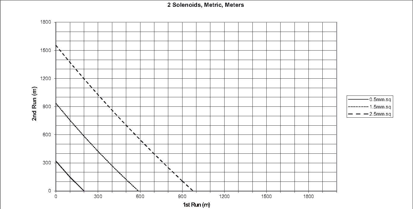
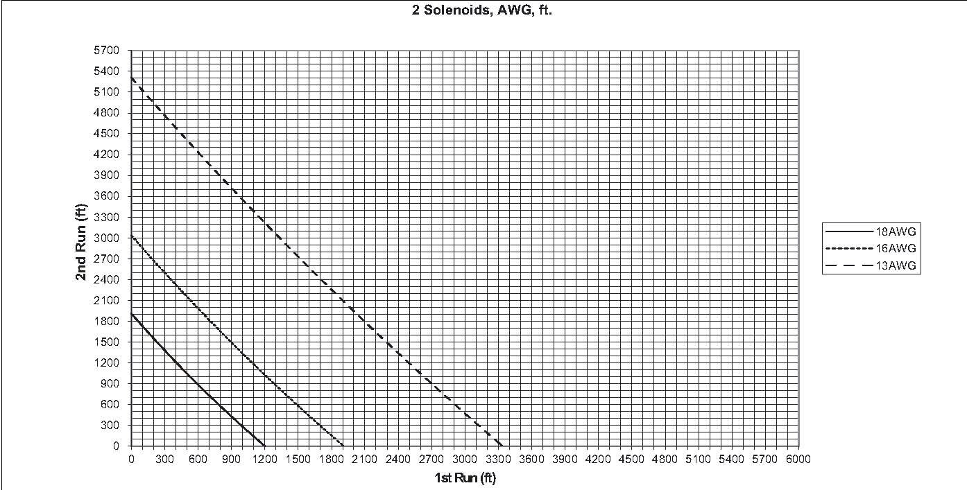
The following two charts (Imperial or Metric), give guidance in choosing the size of the two wire cable when two different stations are on together. More than two stations involve quite complicated calculations, so are not covered here; however an Excel spreadsheet is available called WireMaxRunsStudent.xls.
Basic Assumptions
- No solenoid current reduction scheme is applied.
- Voltage output at the Controller 27V ac
- Minimum voltage to operate a solenoid 19V ac
- Solenoid type Hunter Heavy Duty
- Mains Frequency (the worst case) 50Hz
Instructions for using the charts
- Identify a station that is furthest from the controller that might run concurrently with an even more distant one
- Measure off the cable distance from the controller to the station on the horizontal axis (‘1st Run’)
- Move vertically from there until you intersect the cable line.
- Move left from the intersection until you reach the vertical axis (‘2nd Run’)
- This is the maximum cable length the second, most distant, station from the first to ensure its successful turn on.
For just one solenoid running alone
- At ‘1st Run’ = 0, measure off the cable distance vertically up ‘2nd Run’ to the furthest station.
- If this point lies above the intersection of the cable line with ‘2nd Run’, then the cable is too small.